Just for you, dear reader, this video tells you all about what is going on today.
Friday, August 28, 2020
Saturday, March 7, 2020
Friday, October 4, 2019
The Tool Case Project Part 1
Tool Organising, or The Adam Savage
Obsession – TOOL CASES
Okay I admit it. I watched Adam and
realised that my workshop was hopeless – I don't actually have a
workshop in fact. I need a space that can be organised as a workshop
but more than that, it needs places for all of the tools I use and
they must be organised so I can find them. I have suffered though
moving house and as a result everything shop was packed in cardboard
boxes and shoved in a tin shed until now. Then I decided to start
making things again. I ended up buying tools I already had again
because I didn't even know what I had, and even if I remembered it, I
couldn't find it: a nightmare.
I won't get this problem again if I
make my tool boxes well and so this is that project.
This is not a new idea for me either: I
have been saving some cases from old video equipment I found years
ago for exactly this purpose – they are mainly plywood and even if
I only use the metal corner bits and hinges it will have been worth
it.
I looked at buying tool cases but there
is nothing that meets my needs – either they are impractical, too
expensive or both. Lots of blowmould plastic: Nope. I will be
getting some organisers for parts like nuts & bolts but none of
the tool cases I have seen make sense to me.
I don't really want any big
freestanding tools like a sawbench since I don't expect to do that
much sawing – and I would rather find or make some sort of compact,
folding alternative instead – I know I will have to move house
again sometime and if any item is too big it will just be a burden,
and don't even think about the cost. Those things are expensive.
DESIGN
I first set out some categories for my
tools so that I could decide how many cases and what for:
I came up with six : (1) marking, (2)
drill/tap, (3)saw/file, (4)join/clamp, (5)electrical and (6)paint.
As I learned from Adam, the best cases
can either be sat at the back of the workbench for easy access or
they become the workbench itself – this I intend to do for the
electrical case.
I also want to avoid making layered
cases where you need to open layers to get at the tools behind: that
means you can't see what you have got. Everything should be visible
at a glance.
The cases must also be hand movable
which limits the weight, so I might need to split the power tools up.
It is also a good idea if heavier items should be lower down in the case for stability.
I expect to make them mostly out of
plywood so I will need a saw with straight guides for that: not sure
exactly how that will be done yet. I may need to buy a new tool for this !
There is one more issue to mention:
expansion. I expect to be getting more tools as time passes or
replacing tools that fail, so there must be some room for expansion
and ways to modify or replace the tool clamps as needs arise, so the cases should be like this:
there should be a solid main case body and then tool clamps screwed or otherwise removably attached
to that.
As always I begin the design phase by
measuring and modelling in Blender to get an idea of how things will
be packed in and so forth.
Here are the two basic design ideas as
described:
 |
| Basic case |
 | |
| Case/bench combination |
Yep, that means I now have a whole heap of projects to keep me busy every spare moment - and this one could stall the others for weeks - but it has very good reasons why. I don't ever want to dig through piles of rusty tools for a chuck key again. It's kind of a metaproject: all others will benefit from it.
Special thanks to Adam Savage for reminding me of my maker roots. Maybe other people have their ethnicity or something to identify themselves with, but me? I'm an engineer, a maker.
Monday, September 30, 2019
The Cabinet Part 3
Plans have changed
again. Having swam through a lot of 3D printing vids and blogs I
realised that I really wanted to be able to print flexible and soft
materials for things like tyres,seals etc.
Actually I got right
into the detail and ended up with three basic specifications for
Filament type (FDM) 3D Printing machines:
First, GP/
Decorative – materials are not particularly strong or durable but
the models are high quality finish. Of course, this machine could
also be used for general purpose printing
Next, Strong - this
one needs a high temp chamber and temperature control, materials such
as PE that can be used in high strength applications – but this
needs a lot of specialised equipment to do properly. Prints must be
gradually cooled after printing to keep their shape and there are a
lot of technical challenges.This could get very expensive.
Third, Flexible –
printing soft and flexible materials requires a direct drive printing
head (the filament drive is attached to the hot end) and this is not
common since it makes the printer head heavier and thus the machinery
must do more work to move it around and the process of printing can
be slowed down by this. This is why I suggest a specific machine
just for this type of material.
Actually, I
really like the idea of a dual head machine for flexible materials
since then you could use PVA or something similar for support
material – but that is whole new machine again.
I am not going to
start building a “Strong” machine: that is well beyond my current
needs and abilities due to not having the tools or workshop – but I
can certainly get the other two, which led me to buy a second machine
with direct drive extruder – the Sidewinder X1. This machine has
about the same build volume as the CR10S and good metal construction
but it is a lot cheaper.
It also does not
have auto bed levelling - but I will see about that - it may be possible to add it later.
 |
| Middle space showing 10mm holes for the mid panel nuts. |
To get the middle
panels on it was necessary to drill holes big enough to get the nuts
through and then into the slots in the extrusion bars. The
alternative was to try and attach all three side panels together then
slot them in as one part (not an easy job) and do up the bolts –
but then if you want to take a panel off later all three must come
off. It would also require very accurate hole drilling and my hand
work is good, but maybe not that good.
Since the design has
already changed from my original and the cut panels cost so much I
hope to avoid buying more – so the door for the lower chamber had
to be made from two parts, joined with a strip. I also fitted the
solid feet at the corners this weekend and moved the wheels inside of
them using bars to support them – this is because the cabinet
needs to very solid. This need drove me to order more parts and I
discovered that 45 and 135 degree brackets are available so these
will be used to add three diagonal braces to the bottom when they
arrive. There is only one bolt hole so maybe I will drill extra bolt
holes – but regardless, this will add stiffness.
 |
| Base showing wheels and feet, which can be raised with a spanner. |
When taking these
photos I put the lower door on where it is intended to mount and
discovered that it won't fit flat: the metal right-angle brackets
collide with the nuts on the inside of the door. This can be fixed
with countersunk bolts but it means using a 45 degree chamfer drill
on the plexiglass. Cutting it was bad enough – my first cut was
cracked in five places. Using the right tools makes all the
difference - well, that and being patient. I will need to do a test
drilling or two.
 |
| Cabinet redesign with diagonal braces |
 |
| View from the other side showing air duct system |
The lower chamber will now house the second printer so there is also an air duct for this area too.
I also have a window exhaust duct designed exactly to fit my window and go around the blinds - but of course it needs to be 3D printed !
 |
| Window exhaust duct |
The aluminium
extrusion building system used here was all bought from eBay – all
of the bits from different suppliers, and I am impressed by it: there
are a wide range of sizes of the extrusions, the nuts and bolts,
brackets and various other parts too. I found a store that precut the
bars to my preferred lengths and a supplier for the panels that did
the same, and good thing it was too: I don't have the equipment to do
these cuts myself – well, not as neatly as the suppliers. Because
the parts are all fixed in the slots, you can adjust their positions
as required which is great for flexible projects like this – and
all of the frame parts can be reused later if desired. Nearly all of
the 3D Printers I have seen are made of this extrusion although they
do drill and tap holes in it for solid fixings as well. I have even
seen factory techs in China building automation equipment from this
same system.
There still as lot to do to get it finished - but progress is happening even if I only have about one day a week to work on it. There is also the enforced delay of waiting for ordered parts to arrive - but then there is an advantage to working this way: I have a lot of time to think about everything - as you can see, the design has already changed in major ways. I have also simplified the design since it is then more flexible.
Finally a special
tip of my hat to . . . . . Microsoft. The latest update of Windows 10
includes a screen clip tool that works right – just press
Win-Shift-S and you can snapshot your screen just like on a Mac. Ooop.
Didn't mean to say that – well, since Apple has left us creative
folks out by pricing the new Mac Pro so astronomically that only the
elite can afford one (when it eventually arrives) we must make do -
except that actually it's not at all bad. See my previous posts for
more about going from Mac OSX to Windows 10 if you are interested. It's actually better in significant ways.
Saturday, September 7, 2019
The Cabinet Part 2
Design Ideas
I have been working on cabinet
modifications in spare time – easy to do onscreen, a lot more work
in real.
To print well in stronger materials you
need to be able to get the build area warm but you also need to keep
the electronics cool - and there is also a need to be able to vent
the build area to outside or a filter, so this means ideally you need
four areas:
- build area with a vent valve
- circuitry area with cooling airflow
- intake area
- exhaust area with extractor fan
So here is the idea modelled:


There is also a change I made here
where I put the filament roll directly under the build area – it
just seemed natural to do it that way. This means the bottom of the
cabinet is empty for now but then the whole thing may be too shaky
for normal operation - 3D printing is dependant on having a very
stable surface to operate well – any shake in the table or bench
the printer rests on will result in vibrations of the print head and
this produces “ghosting” - rippled print surfaces.
I will only find out how good the
printing is when it is actually running.
I have identified the air intakes and
exhausts on the CR10S Pro case and thus located inflow cooling ducts
at these two points. This means a lot of small pieces glued together
and I am still unsure how well they would seal onto the CR10S case –
( how airtight do they need to be? ) and also the various parts need
to be accessible and I am not certain how practical this would all
be.
I put the second intake where the power
cord goes into the case so that covers one matter but there is still
the question of just how to remove or replace the surrounding parts
around the printer when things need to be looked at – for example,
at the moment there is no way to access the USB port on the printer
when it is in the cabinet and the power switch will have to be left
on and turned on/off at either the power board or a wall socket. I
might add a door just where the power board is located which would
also have a cutout for the power cord. The power board will also
provide for adding lights and any other powered extras I might add
later.
~~~~~~~~~~~~~~~~~~~~~~
At some point it becomes tempting to
pull the whole printer apart and get rid of the metal case and fix
the frame inside the cabinet, thus all electronics can be in their
own area with isolated cooling. The trouble with this kind of thing
is that I can easily progress to tossing the whole thing out and
building a completely new whizz-bang machine with better, more
expensive parts and I am in danger of starting a big project I may
never finish . . . .
~~~~~~~~~~~~~~~~~~~~~~
Stage 1, or what will definitely
be done for starting the machine and getting it running, is
completing the upper enclosed cabinet with door and fume extractor.
This means cutting a hole in the floor of the chamber and that lead
me to buy some new bars of 2020 to support the printer more directly:
there is some question about how well the panel sheets will take
weight when they get warm and I don't want to cut a hole in the back
wall only to need to patch it up later.
Stage 2 – Getting the printer fully
upgrade with all of the extras I have already bought
Stage 3 - adding the Octopi remote
controller, lights and camera
Stage 4 - improving the cabinet, including relocating the spool holder and addingthe air ductwork.
Sunday, September 1, 2019

Saturday, August 31, 2019
The Cabinet Part 1
 |
| The bare frame |
 |
| lower corners showing brackets |
Here is the frame
complete. I am very happy with this, the parts were all easy to get
and quite cheap considering and it only required the correct tool
tips to bolt the whole thing together.
Actually if you
wanted to you could make anything out of 2020 extrusion and brackets,
it is very strong and easy to assemble.
Okay, it was not
all easy: the corner brackets and the nuts I bought to attach the
panels are special locknuts that can be dropped into the slots in the
2020 then when turned, the nut is supposed to twist and thus lock
into the slots. There is just one problem: they don't always do
that. If the nut is too far up the thread to twist or if the bolt
hole is not exactly in line with the slot, the nut can just sit there
and not twist at all. In the corner brackets you could either mark a
dot on the end of the bolt or even cut a screwdriver slot into it to
not only make sure the other end locks but turn it if it didn't, but
for the panels I had to make do with trial and error, pulling the
panels to see if they were locked on.
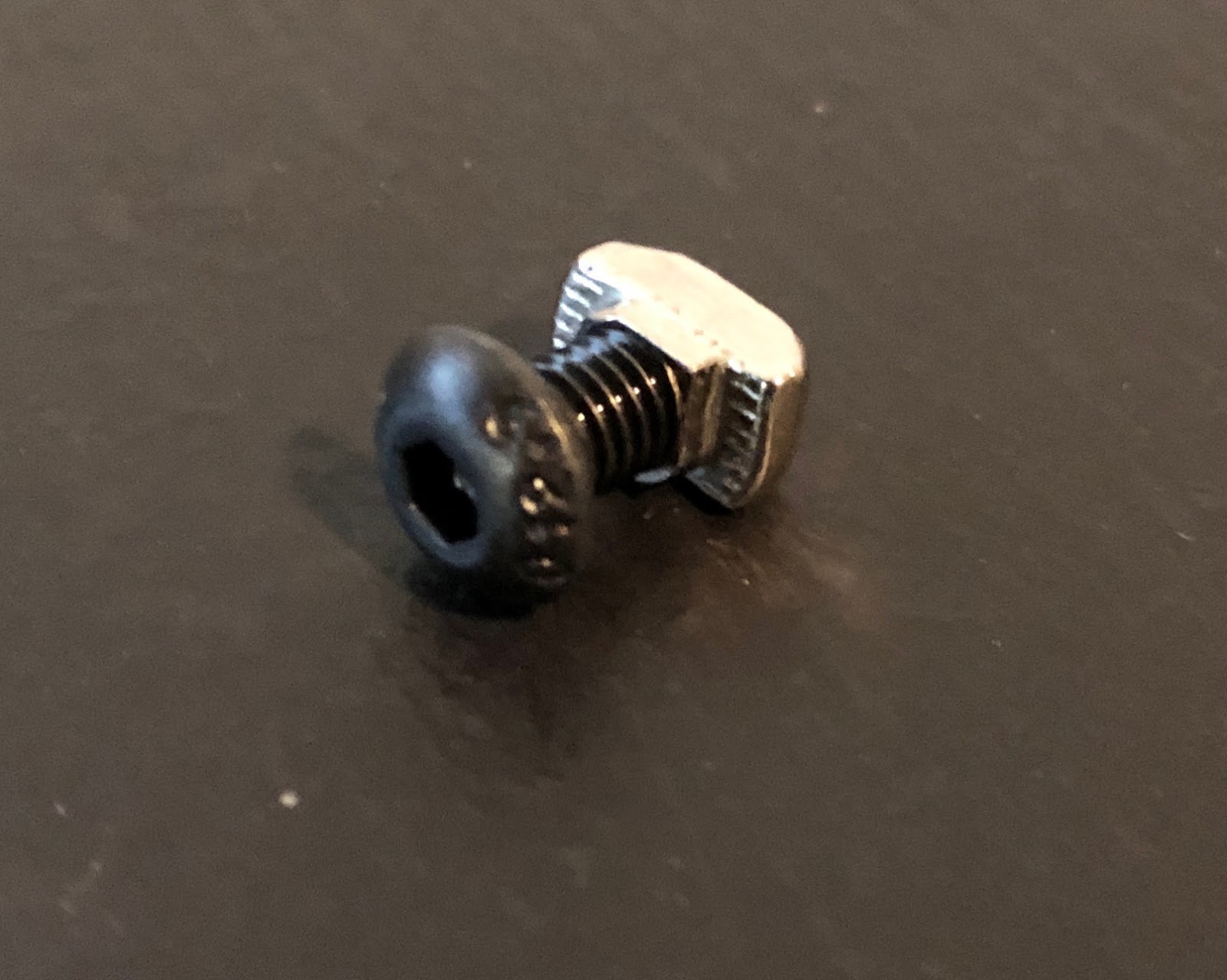 |
| Locknut and M5 bolt |
The panels were a
little more difficult: although the frame cost about $200 the panels
were much more expensive. This was a surprise to me.
For a cabinet
that could take a lot of heat I would have needed metal plates and
glass windows but that seemed to be too hard and not worth it since
the hassle of fitting glass doors with handles and hinges alone would
be a pain. I asked one supplier about 45 degree temperature and
acrylic panels and he replied that glass and metal would be the only
option. I ended up going to another supplier for panels made of
plastic coated in alu and I hope it will be good because along with
cutting the panels it all came to $450 which is serious money.
I don't have any way
to cut the full size panels myself so it wasn't really a choice – I
just liked the metal coated panels better than plain plastic. I think
they will last better.
I actually bought a
lot more connecting parts than needed, that seems to be the norm when
I am working on a project though. Maybe they will end up getting used
later.
The project does
seem to be expanding though.
I fixed most of the
panels to the cabinet today and put wheels on. They make it much
easier to work on. I noticed that the panels need fixing about every
250 mm apart or they will rattle.
 |
| Raspberry Pi with cooler in fornt of my keyboard for scale: it is tiny! |
This is fine apart
from the area where panels overlap: I designed the middle area so
that the panels could be removed easily since that is where the most
complicated bits will be housed: the power boards, raspberry pi and
the air ducting. Since the frame is only 2020 there is one slot for
nuts so at the moment the idea is to drill 10 mm holes in the inner
panels then put the bolts and nuts on the outer panel so the nut
passes right through the 10 mm hole. The hard part is drilling 10mm
holes in the panels without wrecking them: the metal coated plastic
maybe okay but the acrylic clear stuff has a real danger of
cracking. Apparently the idea is to drill gradually bigger holes .
The holes also are only 10 mm in from the edge so after drilled there
will be 5 mm of edge left. I will have to test drill some scrap
first to see how well it turns out.
 |
| Cabinet with wheels and some panels |


A major reason I got the CR10S Pro is that it has automatic bed levelling out of the box. If there is one thing you do not want to spend time doing it is levelling your printer bed. This auto leelling depends on a sensor stached to the print head that detects the bed very accurately. The CR10S comes with a capacitive sensor and some folks online have compained about it being inconsistent especially when delaing with hot build plates or other variables. I am also concerned because I am going to replace my build plate with the magnetically "stuck" WhamBam plate - so my answer is to get the reputedly more reliable BLTouch sensor which has a small retractable pin that literally touches the bed to detect it. Tehre is also a video showing how to fit it and a special firmware version available for y specific model of printer which made it a sure thing for me.
I bought a BLTouch
sensor from 3D
Printing Canada who also have a good video on how to fit it to a
CR10S Pro – but it was $137.
There was supposed to be a local
firm selling them but they are now calling themselves “Wombot” and selling 3D printers draped in Aussie flags - and they are covering their
machines with the same metal/plastic sandwich panels as my cabinet.
Their cheapest machine starts at $5k and I am curious to see a review
of their products since that seems way more expensive than
anything else: perhaps they are aiming for the “professional
market” but I can't see that as being viable. Still, what do I
know? Perhaps their support will be fabulous and they will outsell
all other machines locally. I can't see that happenning myself since
the market for serious 3D printers is limited and the big guys
(Stratasys etc.) have it pretty much stitched up. Is there a market for
more average, small fab machines costing that much? It seems to me that I have seen this all before.
So there it is: What are people doing with their 3D Printers? Making Cosplay Ironmek (Don't wanna get sued here) outfits? I'm still not exactly sure what I will be doing with my machine once it is running smoothly, but I have a few ideas.
All suggestions welcome.
All suggestions welcome.
Subscribe to:
Posts (Atom)