Monday, May 8, 2023


THE CNC PROJECT


Part 3


DRAG CHAINS


What are drag chains? 

 They are a sort of hollow chain that is used to carry the cables from the fixed part of a machine to the moving part while protecting the cables and stopping them from getting tangled up.

The OneFinity I bought did not come with any and I wanted to add a milling spindle with water cooling so I bought some and made my own mountings to fit them to the 1F. 

I first looked at what other people had made on the 1F forums and one person was selling 3D printed drag chain fittings - but when I looked at them I was not happy.

There are three parts to such a set: the Top Mount, the X End Bracket and the X Bend Mount that curves all of the cables 90 degrees and then runs them into the second drag chain which goes to the benchtop.

This is his Top Mount:


I may not be a qualified engineer but I am pretty sure bending cables back 180 degrees is not a good idea.

Here is his X End Bracket and X Bend Mount:


Not bad but I think I can do a lot better. I also want to make sure that my cooling pipes from the spindle are smoothly routed as any sharp bend will restrict the flow.

I started with cardboard and sticky tape: I stuck the bits onto the machine with masking tape and marked where things went and fiddled with things until it all worked right, then drew the shapes carefully with compass and rulers.

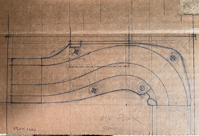
Here is my pattern for the most important part, the X Bend Mount:


The idea is that the fluid pipes will go round the outside of the curve with the wires on the inside. The side walls are to be built up in two layers of 5mm thick ABS sheet while the bottom is 2mm ABS sheet.

The mountings use “L” shaped bits of the same 2mm sheet and three are used – two for the Bend mount and one for the end mount that is only there to support the aluminium rails that the drag chain rests in.

Here you can see the patterns and the parts ready to be cut from the sheet:


On the left are the side wall patterns and below them the bracket pattern.

The parts were first roughed out and then the sidewalls were glued together to final thickness before lots and lots of cutting, filing and sanding.

Note that the glue faces must be sanded first and cleaned to get a good gluing. I used “superglue” - I have some experience with it.

Note also the use of masking tape to allow drawing on black plastic sheet, an otherwise impossible task.

The mounting brackets needed two bolt holes in them so I drilled these and used the holes to bolt all three together for easier shaping.

During the production some details of the design chainged but that is normal and the main parts were checked repeatedly to make sure they would fit as planned.

This took some time but I think it all came together quite well.


Here are the finished parts: On the left, the X End Bracket, right is the X Bend Mount and below is the Top bracket.


My brackets have a step for the drag chains to mount on so that the cables run smoothly on and off the chains.

The Top bracket has a magnetic fitting under it where a clip for the dust boot pipe fixes on – you can see the magnet in the picture.


Here is how they look fitted to the machine: you can see the rails that the drag chain rests in on the X axis. Yes, I know it’s not all polished but I don’t care: it’s not worth the trouble for a piece of industrial machinery.


When the pic was taken I was getting the rails for the Y chain ready to be fitted. They are “L” profile alu extrusion screwed to the benchtop.

You can also see back end of the dust shoe I bought to run the suction back and behind the drag chain rails. More about that in part 4.

Here is another view of it, this time with the cooling pipes fitted and . .

a rope.


How do you get the cables and pipes into the drag chains?

This is my answer.

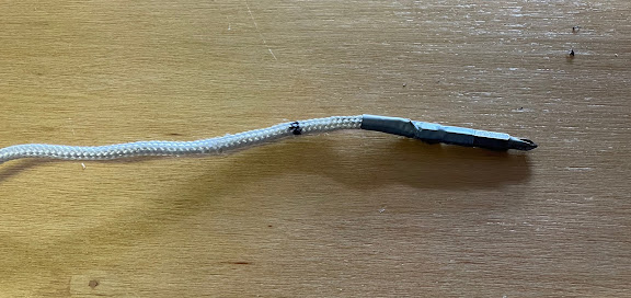
Get a rope and a driver bit. I used a phillips bit as it was less likely to catch on anything. It had a narrow collar near the back and I used a small bit of thin iron wire to fix it to the end of the rope and then covered it all with duct tape to make a smooth outside.


The last part is a good strong magnet.

I threaded the end into the drag chain and then use the magnet to pull the driver bit along inside the chain from outside. When I got to the bend I went right up to it, then moved the carriage so the bend went past the driver bit then carried on pulling it with the magnet to the end. 

 Now the rope is all the way through and you can fix your cable to end of the rope and pull it gently through. Note that this really only works well with bare ended wires – you need to add the plugs etc. after threading.

Here is the same X Bend Mount in a more finished state with the cable cover plates fitted. The X motor cable runs over top and through the small white clip.


Finally, here is where the cables and pipes run through the benchtop:

I bought a lot of grommets and plugs for this project and here you can see some of them.

 See you in part 4


THE CNC PROJECT


Part 2


DUST AND MORE DUST


All milling machines make dust – or swarf, or shavings or whatever you want to call it, but the faster they work and the better they cut, the more dust they make and you better have a way to clear that away for your milling head or it will clog up, overheat and maybe even break a tip.

So you need a dust collection system.

Yes, you could just get a shopvac but that won’t cut it: once the vac bag gets about half full its suction drops off and you are forever going to be buying new dust bags, and this thing is going to be sucking a lot of dust over long periods.

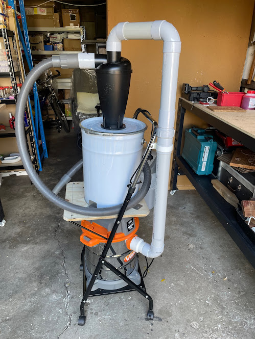
What works so much better is a cyclone filter. This is a specially shaped chamber that causes a “cyclone” in the air that gets the particles in the air to drop out. This goes in front of the vac so that the air being sucked into the vac is almost clean while all of the dust is easily collected out the bottom of the cyclone.

At first I thought of putting the whole thing under the CNC but this is a very useful thing to have: almost every workshop power tool makes dust and they have a collection port that you can hook up the vac to, so why not have it on a mobile trolley for general use?

The cyclone cost $32. The Shop Vac was $100. Other than that there were some bits of 50mm PVC plumbing and a metal 20L drum I found for free at my work. I had a trolley that I got for some other use that just happened to be exactly big enough to fit the shop vac on the bottom shelf. I estimate the total cost at $180.

Just have a look at how much the fancy shop vacs go for and note that these do not usually have cyclones on them: you will be buying a lot of dust bags if you want to use them for a CNC mill.

The big pipe has a threaded joiner in the middle that acts as a swivel so that the top can be removed from the cyclone (the black bit) and the drum has a clamp on it that can be undone to get the dust emptied. The fitting on the bottom that locks onto the vac has a swivel that is airtight and has slots that lock on the pins on the vac body so you can remove the bits above it easily to empty the vac itself (although this won’t be often).

There are other neat details but the main thing is that it all works well. See the picture below.


As a project this worked out really well. It made me think and it was good practice putting various parts together to make something that works properly.

It also kept me going while I waited for parts of the CNC to arrive.  There was a lot of waiting involved.


Sunday, May 7, 2023


THE CNC PROJECT


Part 1


Overview

What I really want is to make nice clean things that work because the parts all fit together neatly. I want to make some spinning motors and such in future and that needs high quality accurate machining. It will take time to develop, yes, but the results will be usable as opposed to rough-as-guts hand manufacture. I know that only too well.

The best way to do this is with a CNC Mill. That’s Computer Numerical Control. When I worked in a machine shop as a teenager the CNCs were big and expensive. We cut stainless steel like it was cheese.

Nowadays there are small, cheap and low power models that you can run from your garage. This is defined as subtractive machining – you take a lump of material and subtract the bits you don’t want from it. The opposite is additive machining, or 3D printing. I have one of those too – they are good but the parts it makes cannot equal the strength of a machined aluminium part. Having both in your workshop is the best option.

I looked around the net and after careful thought I decided on the OneFinity Woodworker X-50 32 x 32 inch. It cost about $5K AUD including delivery from Canada.


Why did I choose the OneFinity?

1. Ball screws. It has Ball screws which are solid unlike a lot of other machines which have belts. Belts are fine for machinery that does not take a lot of force such as 3D printers, but for milling they are just too weak imo.

2. Solid construction with linear bearings. This is the only home CNC that has decent rails and lead screws.

3. Flexibility with the choice of machine head and software.

The maker does not recommend using it for cutting steel and that is fine. They also don’t supply a milling head or drag chains and that’s fine, I will get my own. They supply the three motion axes, the controller box for them and the control panel. There are a few extras that are worth getting from OneFinity such as the touch probe but everything else you get for yourself and assemble yourself.

So now there is a whole lot of work to get all of the parts together and assemble them into a working machine - metalwork, woodwork, electronics, plastic work, painting, design . . . . there’s all of them needed and a few other things too. Then once it is all working I need to work out the software to make it all go.

I actually started the whole thing in august last year. There has been a lot of time spent waiting for parts to arrive and a lot of frustrations when things did not go according to plan, but now it's looking pretty good.


The Bench

The machine needs a solid bench and I bought one, twice.

The frame of the bench needs to be solid and it looks like the best one is made by a company called Kreg. It comes in parts that bolt together and it is thick steel – but for some reason they are very hard to get here in Oz. The first time I ordered it they refunded me a week or two later because they could not get one.

I ended up having to buy a smaller one just for the vertical legs and a set of long horizontal bars direct from the US. It was worth it though, I did not see any other item that was as solid.

I tried out other options -  (getting cheap chinese metal benches and widening them) - but they were so flimsy and wonky that the bench would never have been stiff enough to use. They are okay for what they are – I have three in the garage, but no good for mounting the CNC on.

Then there was the bench top.

I could not get plywood thick or wide enough for my initial plans so I ended up getting thinner 12mm sheets, redesigning things so the bench was only 1220 deep (max plywood width) and then gluing two sheets of the ply together to make one solid plate 24mm thick to mount the CNC on.

I don’t recommend this to anyone: with no proper tools or even a bench 1220 x 1300 to sit them on it while gluing it’s surprising that they turned out okay. Even then the whole thing is not quite flat: it has a slight bulge in the centre.

I had hoped that gluing them together would flatten it but nope.

Now that the machine is bolted to it I will use the machine itself to mill the middle of the bench flat before I put the spoil board on.


Other bits

I added a lower level shelf from some bits of a cheap metal bench and another piece of the same plywood to stabilise the bench a bit and give me somewhere to put other parts of the machinery out of the way – the electronics, the water cooling system for the milling head and the suction hoses and so on.

------------------------------------------------------

The plan

I didn’t just throw all of this together, I made plans from the start – and I designed, re-designed and re-re-designed things in 3D using Blender, my preferred design tool.


This is version twentyfour of the Blender model, and for reference below is a photo of the real thing : Not too far off. The cover frame is only a test fit here.

I am missing out a lot of the details here, trying to give a short report on a very long and drawn out project. This is where I spend my weekends.


More soon in Part Two. Thanks for reading.