THE CNC PROJECT
Part 3
DRAG CHAINS
What are drag chains?
They are a sort of hollow chain that is used to carry the cables from the fixed part of a machine to the moving part while protecting the cables and stopping them from getting tangled up.
The OneFinity I bought did not come with any and I wanted to add a milling spindle with water cooling so I bought some and made my own mountings to fit them to the 1F.
I first looked at what other people had made on the 1F forums and one person was selling 3D printed drag chain fittings - but when I looked at them I was not happy.
There are three parts to such a set: the Top Mount, the X End Bracket and the X Bend Mount that curves all of the cables 90 degrees and then runs them into the second drag chain which goes to the benchtop.
This is his Top Mount:
I may not be a qualified engineer but I am pretty sure bending cables back 180 degrees is not a good idea.
Here is his X End Bracket and X Bend Mount:
Not bad but I think I can do a lot better. I also want to make sure that my cooling pipes from the spindle are smoothly routed as any sharp bend will restrict the flow.
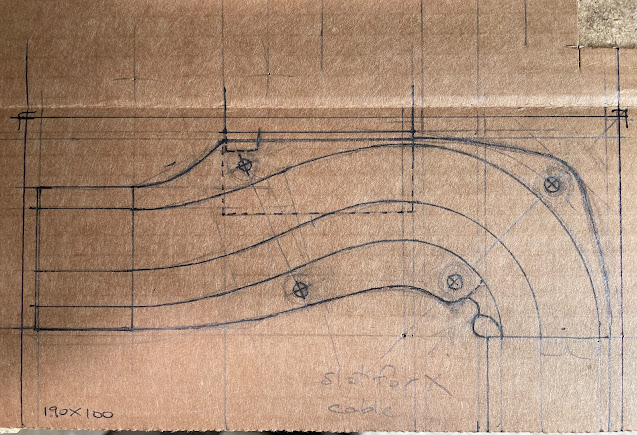
I started with cardboard and sticky tape: I stuck the bits onto the machine with masking tape and marked where things went and fiddled with things until it all worked right, then drew the shapes carefully with compass and rulers.
Here
is my pattern for the most important part, the X Bend Mount:
The idea is that the fluid pipes will go round the outside of the curve with the wires on the inside. The side walls are to be built up in two layers of 5mm thick ABS sheet while the bottom is 2mm ABS sheet.
The mountings use “L” shaped bits of the same 2mm sheet and three are used – two for the Bend mount and one for the end mount that is only there to support the aluminium rails that the drag chain rests in.
Here you can see the patterns and the parts ready to be cut from the sheet:
On the left are the side wall patterns and below them the bracket pattern.
The parts were first roughed out and then the sidewalls were glued together to final thickness before lots and lots of cutting, filing and sanding.
Note that the glue faces must be sanded first and cleaned to get a good gluing. I used “superglue” - I have some experience with it.
Note also the use of masking tape to allow drawing on black plastic sheet, an otherwise impossible task.
The mounting brackets needed two bolt holes in them so I drilled these and used the holes to bolt all three together for easier shaping.
During the production some details of the design chainged but that is normal and the main parts were checked repeatedly to make sure they would fit as planned.
This took some time but I think it all came together quite well.
Here are the finished parts: On the left, the X End Bracket, right is the X Bend Mount and below is the Top bracket.
My brackets have a step for the drag chains to mount on so that the cables run smoothly on and off the chains.
The Top bracket has a magnetic fitting under it where a clip for the dust boot pipe fixes on – you can see the magnet in the picture.
Here is how they look fitted to the machine: you can see the rails that the drag chain rests in on the X axis. Yes, I know it’s not all polished but I don’t care: it’s not worth the trouble for a piece of industrial machinery.
When the pic was taken I was getting the rails for the Y chain ready to be fitted. They are “L” profile alu extrusion screwed to the benchtop.
You can also see back end of the dust shoe I bought to run the suction back and behind the drag chain rails. More about that in part 4.
Here is another view of it, this time with the cooling pipes fitted and . .
a rope.
How do you get the cables and pipes into the drag chains?
This is my answer.
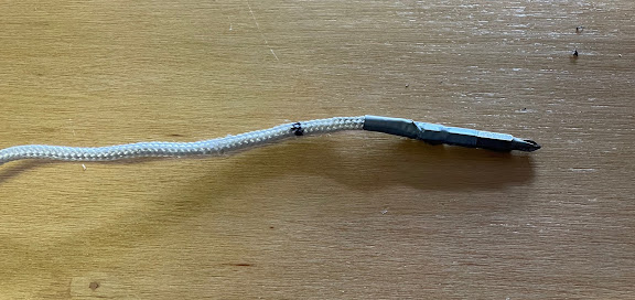
Get a rope and a driver bit. I used a phillips bit as it was less likely to catch on anything. It had a narrow collar near the back and I used a small bit of thin iron wire to fix it to the end of the rope and then covered it all with duct tape to make a smooth outside.
The last part is a good strong magnet.
I threaded the end into the drag chain and then use the magnet to pull the driver bit along inside the chain from outside. When I got to the bend I went right up to it, then moved the carriage so the bend went past the driver bit then carried on pulling it with the magnet to the end.
Now the rope is all the way through and you can fix your cable to end of the rope and pull it gently through. Note that this really only works well with bare ended wires – you need to add the plugs etc. after threading.
Here is the same X Bend Mount in a more finished state with the cable cover plates fitted. The X motor cable runs over top and through the small white clip.
Finally, here is where the cables and pipes run through the benchtop:
I bought a lot of grommets and plugs for this project and here you can see some of them.
See you in part 4


No comments:
Post a Comment